Let's Make a CPU: Part 2 - NAND Logic and Addition
by dweller - 2017-03-14
Previous part. If you missed the introductory post, head here: Part 0.
Last time we made NAND gate, now it’s all fun and cool, but in order to proceed we need all the other Boolean operations. And as we found out last time, we can create them from our magical NAND gate.
But first things first. We don’t want to look at the transistor schematic of the NAND gate all the time. As we make more and more complicated circuits it’s just going to be a mess.
So let’s use so called Shaped icons for our logic gates (IEEE Std 91/91a-1991).
Meet NAND:
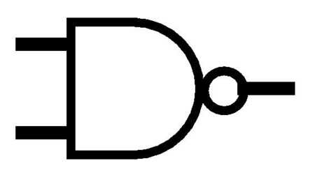
You can think of this as an interface of our NAND implementation, a black box. Imagine that the inputs and outputs are connected with our CMOS NAND implementation inside:
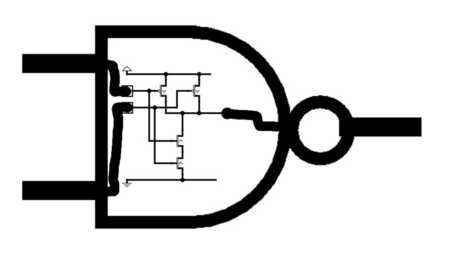
Okay so now that we got that out of the way, let’s start with simple NOT gate. It has only one input and it simply outputs inverted version of it.
NOT truth table:
| a | out |
|---|---|
| 0 | 1 |
| 1 | 0 |
Let’s also bring back the truth table of NAND gate again:
| a | b | out |
|---|---|---|
| 0 | 0 | 1 |
| 0 | 1 | 1 |
| 1 | 0 | 1 |
| 1 | 1 | 0 |
Spotted anything? That’s right, when a and b are the same we effectively invert one of them! So let’s just connect a and b as single input. And voila!

To make our lives easier in the future, we’ll assign a symbol for NOT just as we did for NAND.
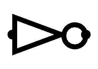
Okay that’s great, now that we have NOT we can invert signals, which is quite useful. For example, to make AND gate we just need to negate the NAND gate, like this:

And the symbol for AND is:
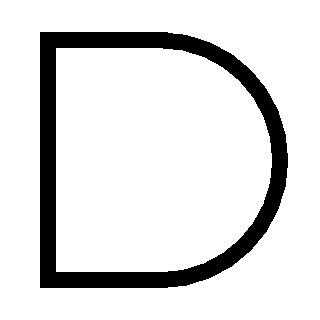
We’re doing great! Now let’s make OR gate. OR gates return 1 if any or both inputs are 1. We can achieve this pretty easily by just negating inputs to our NAND gate.

This works because, if you look at the truth table of the NAND gate, we basically turned the inputs on their head, leaving the outputs the same.
| a | b | out |
|---|---|---|
| 1 | 1 | 1 |
| 1 | 0 | 1 |
| 0 | 1 | 1 |
| 0 | 0 | 0 |
And the symbol for OR is:
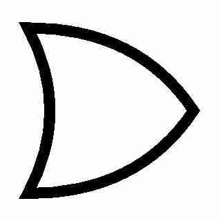
With all that done, we can implement one of the coolest gates ever! XOR gate, or eXclusive OR. To make it, first let’s look at our trusty truth table:
| a | b | out |
|---|---|---|
| 0 | 0 | 0 |
| 1 | 0 | 1 |
| 0 | 1 | 1 |
| 1 | 1 | 0 |
Aha, so it works just like OR, except when both inputs are the same it’s 0. We can use OR gate to implement the first 3 rows of the table. The last row looks awfully familiar to last row of NAND gate, so let’s also use that. Now we need to combine the results together. If we simply use the AND gate we can see magic in action.
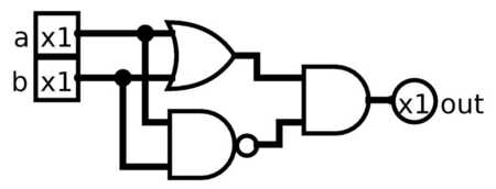
It’s not magic though, this will return 1 only when both NAND and OR produce 1. Effectively we’re masking excessive positive outputs of these gates. In fact AND is often used to mask things to 0.
The symbol for XOR is this awesome starship like shape:
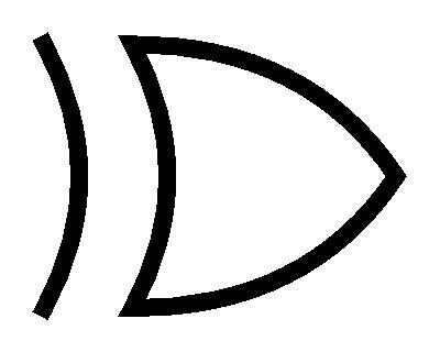
Now this is podracing amazing and stuff, but we are nowhere near the implementation of the CPU, and we already spent considerable amount of time. But don’t worry, I left the best for dessert.
Here’s a nice property of XOR, it’s just like addition, just binary.
0 + 0 = 0
1 + 0 = 1
0 + 1 = 1
1 + 1 = 0
“Wait what? 1 + 1 is 0? I think you stared to long at circuit traces there.” - some of you might say. And you would be right, if not for carry. See we are in binary here. Base 2. All we have to work with here are 0s and 1s. So to represent number like 2 (Base 10, also known as decimal) in binary we need two digits. 10 in Base 2 is 2 in Base 10. It’s just like when you run out of digits in decimal, you carry the 1. For example, 4 + 1 = 5, but 9 + 1 = 10 (All Base 10 here).
So if we produce a carry we would make a 1-bit adder. Let’s make a truth table.
| a | b | carry | sum |
|---|---|---|---|
| 0 | 0 | 0 | 0 |
| 1 | 0 | 0 | 1 |
| 0 | 1 | 0 | 1 |
| 1 | 1 | 1 | 0 |
As we can see, for sum output all we need is XOR, and for the carry all we need is AND. Pretty easy.
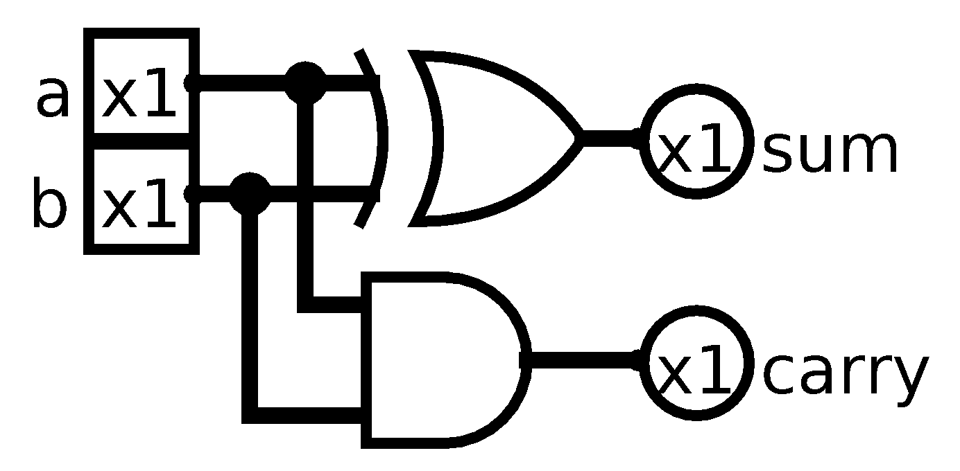
To make sure, lets ask Logisim to generate a truth table.
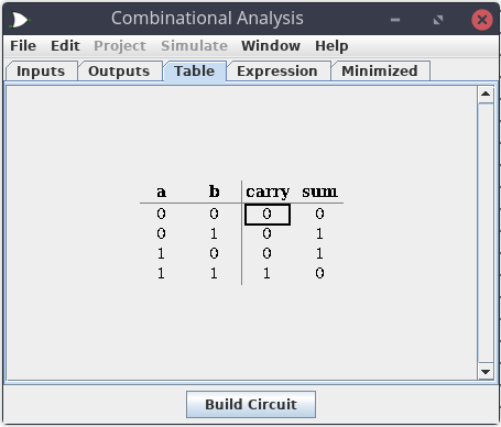
Great! What we created is called Half Adder. Why half? Well, because it doesn’t care about previous carry. So even though it generates it, in the next iteration of computation it won’t consider it.
So let’s step up our game, let’s create Full Adder! Here come the good news. We can make Full Adder by using two Half ones. Makes sense, half + half = full. Hmm, come to think of it, maybe that’s why they are named like this. Anyways, all we need to do is to add sum of a + b to input carry and then OR output carries of each of that additions.
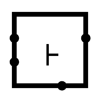
Before that, to make our lives easier once again, let’s encapsulate our Half Adder into a box. Since it’s not in IEEE standard we used for our Shaped gates. We can make it look however we want (within reason and what Logisim allows us to do).
I made mine a box with half of the ‘add’ sign:
Now let’s look at the Full Adder implementation:

And check its correctness with Logisim.
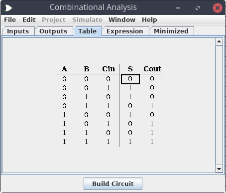
Awesome! Looks like we can now add bits together! Aren’t you excited yet? No? Just me? Well you should! We just made our first step, we can compute sums. Yeah, yeah. It’s only for two 1 digit, binary numbers with carries, but hey.
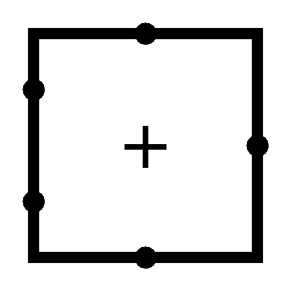
Oh and let’s also create a symbol for our newly baked Full Adder:
Pheh! That was a lot, wasn’t it? Next time we will finally move into 8-bit territory, excited? I am! We will start creating the heart of the computation in the CPU, the number cruncher, the ALU, or Arithmetic Logic Unit!
P.S. Noticed how Half Adders clicked together to form Full Adder, I wonder how we will make 8-Bit Adder. Hmm… ;)
P.P.S. If you find any errors, or want to give me some feedback, feel free to send me an email