Let's Make a CPU: Part 3 - 8-Bit Integers, Two's Complement, and ALU Design
by dweller - 2017-03-23
Previous part. If you missed the introductory post, head here: Part 0.
Preface: I decided to ditch my plan for Part 3 as monolith part that covers all aspects of our ALU. It’d be too long, and I found myself cutting some interesting, yet non-essential parts out. That seems stupid to me, because with approach like that you may as well just search for ALU schematic online and be done with it.
Instead I will break topics up into more parts, and talk a bit more in depth about some parts of ALU.
Last time we left off with a Full Adder on our hands, as well as, with dreams of 8-bit glory. So it would be fitting to scale up our adder into this new and exciting territory.
First let’s check out our Full Adder again:
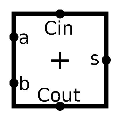
As you can see, I added text near the pins for ease of distinguishing.
Now, as some of you might’ve guessed from my tip in the last part, in order to go 8-bit with our little adder all we really need to do is stack’em one on top of the other. To be more precise, You take two 8-bit inputs and a 1-bit carry, you split the inputs and feed them into into 8 1-bit Full Adders, you also connect all the carries, and- Well, just check the picture, it’s pretty self-explanatory:
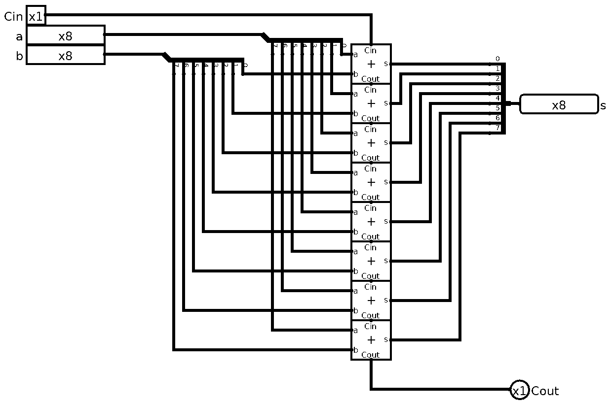
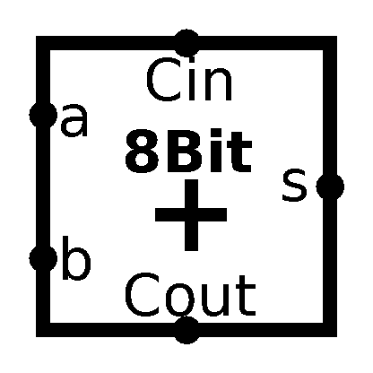
This is called Ripple-Carry Adder, because if you put the adders horizontally instead of vertically like I did, the carries ripple from output of one into input of another, like wave. There are other ways of creating an adder, more optimized and efficient. One example of those are Carry-Lookahead Adder. I won’t cover those here, because I think Ripple-Carry Adder is very easy to understand and is sufficient for our purposes of toy-CPU. Anyways, let’s make a symbol for our newly baked 8-bit adder:
Now, Logisim can’t create truth table for schematics with multi-bit I/O. Sad. But, we can test it ourselves. From this point on, I will provide Logisim schematic file, but if you are really interested in this, you’d be better of doing this along with me.
Okay so we can add 8-bit integers, now what? How would we, say subtract 2 integers? This is very good question to ask, but in order to answer it, first we need to ask another question. How do we even represent negative numbers?
So far we only worked with unsigned integers. Actually what we worked and will always work with are simply bit patterns. We assign meaning to them ourselves by doing specific operations on them. This is very broad topic (Type Theory) that we won’t cover here, because it’s way out of our abstraction level. But we do need to provide some basic operations in our CPU, so we need to interpret those bit patterns as something at some point. Like our adder for example, interprets them as unsigned integers. Our future Logic part of ALU needs to interpret them as Booleans. But for real world applications limiting ourselves with only unsigned integers is not practical. So we need a way to distinguish between unsigned and signed integers.
So how do we do it? Well, let’s explore a bunch of ways to do that:
Sign and magnitude.
If we make our most significant bit (MSB) of a byte a sign bit, we can simply define that 0 is positive and 1 is negative. The rest of the byte is the magnitude of the number.
Keep in mind that we number bits inside of a byte from right to left, so MSB is most left bit.
      7       0
Byte: 0000 0000
      ^
      Most significant bit
For example, in signed 3-bit system:
| Base 10 | Base 2 |
|---|---|
| 0 | 000 |
| 1 | 001 |
| 2 | 010 |
| 3 | 011 |
| -0 | 100 |
| -1 | 101 |
| -2 | 110 |
| -3 | 111 |
“Wait, what in the name of Turing is negative zero?” I assume some of you might’ve thought this way.
Yeah, this is really not cool, but this is how we defined it. The benefit of this system is that it is easy to get for humans, in real world we are used to stick - before a number to represent that it’s a negative one. It also means that we will need to handle the sign in our adder and subtractor. But let’s check another systems before we commit ourselves.
One’s Complement.
In this system we represent negative numbers by inverting them, aka applying bitwise NOT on them. For example 2 is 010, so -2 would be 101.
So let’s check it out in our 3-bit system:
| Base 10 | Base 2 |
|---|---|
| 0 | 000 |
| 1 | 001 |
| 2 | 010 |
| 3 | 011 |
| -3 | 100 |
| -2 | 101 |
| -1 | 110 |
| -0 | 111 |
“That didn’t fix anything, though!” - readers.
Yep, it just changed notation. But this one also has a perk. You see, we don’t need to change our adder much. If we want to add 2 signed numbers we use the same adder we already have and just add back carry to it.
Adding two positive integers doesn’t change at all with this:
  Base 2      Base 10

     001            1
  +  010      +     2
     ---          ---
     011            3
  +    0      +     0 (carry)
     ---          ---
     011            3 (as expected)
Now let’s add positive and negative numbers:
  Base 2      Base 10

     110           -1
  +  010      +     2
     ---          ---
     000            0 (incorrect)
  +    1      +     1 (carry)
     ---          ---
     001            1 (as expected)
Now it’s very awesome and cool, saves us building specialized signed adder, but that negative zero is really bothering me. Let’s look at yet another representation.
Two’s Complement.
What if I told you, we can take One’s Complement and put it on steroids? By that I, of course, mean let’s do the same thing we did in One’s Complement and add 1.
What we do here is effectively shift our problem. We make negative zero go away. Don’t believe me? Watch.
First let’s see how the numbers look. Remember to represent numbers in this system we invert the number and add one. For example 2 is 010, so -2 would be 101 + 1 = 110.
So in 3-bit two’s complement system:
| Base 10 | Base 2 |
|---|---|
| 0 | 000 |
| 1 | 001 |
| 2 | 010 |
| 3 | 011 |
| -4 | 100 |
| -3 | 101 |
| -2 | 110 |
| -1 | 111 |
See, no negative zero! But how?
Let’s try to represent negative zero in two’s complement: 0 is 000, so -0 is 111 + 1 = 000. Wow. Right? Granted we do have carry 1, but we don’t use it. So we just solved our double zeros problem with one magic trick, “Computer Scientists hate it”.
Leaving clickbait behind, we also retain the benefit of having same adder for signed and unsigned integers, even better we don’t need to add carry back.
Okay now so I assume y’all agree with me here that Two’s Complement is the best out of these three, so we will use this one. And now that we finished our theory lesson for this part, let’s finally answer our original question: “How would we, say subtract 2 integers?”
First of all let’s remember some basic base 10 math. Subtracting, say, 5 from 10 is the same as adding -5 to 10. aka 10 - 5 = 10 + (-5).
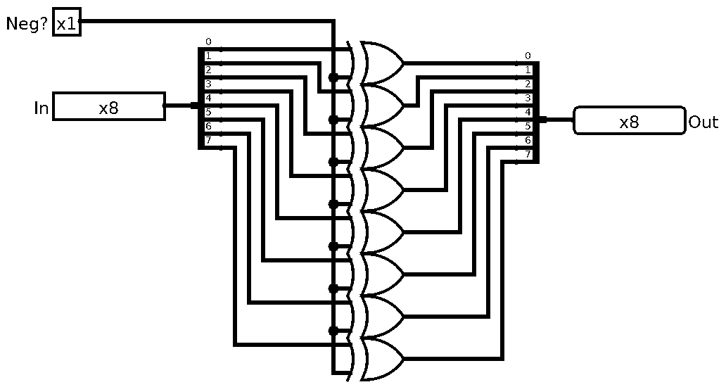
So if we convert our number to negative before adding it, we can subtract it. Sounds easy enough, all we need to do is to send all 8-bits through NOT gates and then add 1. Wait so we need an adder in adder, or 2 cycles to do this? Nope, remember that we have Carry In input in our adder that is added to the result of a + b inside. Awesome!
But, before we do that, one more thing. Instead of using NOT gates, let’s use XOR. Why?
Since our Adder is our Subtractor we want to choose the mode of operation. So let’s add an input called Sub? that will select either add or subtract modes in our Adder/Subtractor. We can use this same input as Carry In to add that 1 for transforming the number into negative. We also can use it as an input to our XOR gates to flip bits only when we need to subtract! This works because of properties of XOR gates. If you recall, XOR returns 1 only when inputs are opposite. So we can flip one of the inputs with the other. (Check the XOR implementation in previous parts for reference.) Incredible!
Let’s take a look at the “negator” circuit:
And as always, let’s abstract it away and hide it under it’s own symbol:

Now we can make our Adder/Subtractor. But, again, let’s talk a bit before we do that.
Since we are working with finite amount of bits we cannot represent all the numbers. With 8-bits we can represent unsigned integers from 0 to 255 (2^8 - 1 we subtract one because we start from 0) and because of the two’s complement we can express signed integers from -128 to 127. So what happens when we say add 1 to 255? Let’s check it out, shall we?
       Base 2      Base 10

     11111111          255
  +  00000001      +     1
     --------         ----
  1  00000000            0
  ^
  Carry
This is called an overflow, we ran out of bits to store the number. We can detect this if we actually do not ignore the Carry, so it would be good if out Adder/Subtractor outputted it so we can save it in fufure.
Detecting overflows in signed computation is a bit more involved. Consider next:
       Base 2      Base 10

     01111111          127
  +  10000001      +  -127
     --------         ----
  1  00000000            0
  ^
  Carry
This is actually correct, but if we assume Carry is sign of overflow we’d make a mistake, here it’s better to ignore it. Let’s look at this:
       Base 2      Base 10

     01111111          127
  -  10000001      -  -127
     --------         ----
  0  11111110           -2
  ^
  Carry
This clearly wrong, 127 - (-127) = 127 + 127 = 254 we can’t represent that large of a number in two’s complement 8-bit signed integer. So it’s an overflow, but Carry is 0!
We need to detect this too somehow, and it’s actually pretty easy. If the sign bits (Most Significant Bits) of our inputs do not match the carry we’ve got overflow on our hands. It is important to note that we get the MSBs after we negate 2nd input, we only check this for actual addition.
I know you are itching to see the complete circuit, so here we go:
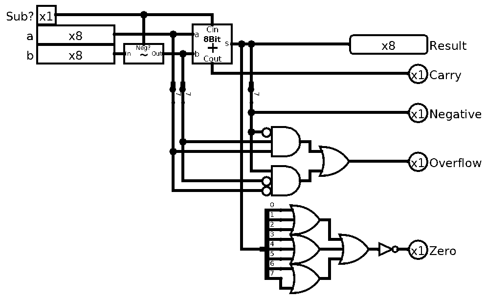
So there are two things I’ve left unexplained. And both are pretty much self-explanatory. The zero and negative “flags” are necessary when we want to check things. Like if a is bigger than b. We can check it by subtracting b from a and seeing if result is negative, but we are getting ahead of ourselves.
The negative flag is simply set by MSB of the result. The zero flag is a bit more involved, but it is simple enough. All we need to do is OR all the bits, if any bit is 1 the result is 1, if all bits are 0 it’s 0, but since we want flag raised or set to 1 when all bits are 0 we simply NOT it to flip it. Easy.
And as per tradition, after all this hard work, let’s abstract it away:
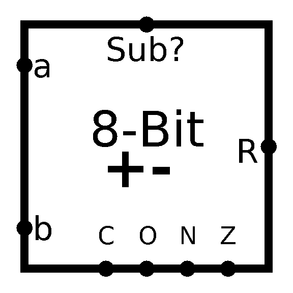
So that’s that, phew, that was involved. But, I for one, think it was really cool. It makes one to appreciate how things work inside of our computers, and we are not even close to done! Just imagine how much stuff is going on inside today’s 64-bit CPUs!
Anyways, so next time we will continue building Arithmetic part of the ALU, and hopefully finish it!
Oh, and here’s the Logisim circuit: cpu-scratch-p3.circ
P.S. I recently saw this amazing talk by Todd Fernandez about how we actually produce nano-scale transistors. I highly recommend you to give it a watch: youtube.com I can’t recommend it enough.
P.P.S. If you find any errors, mistakes, and/or want to give me some feedback, feel free to send me an email