Let's Make a CPU: Part 4 - Finishing ALU
by dweller - 2017-05-07
Previous part. If you missed the introductory post, head here: Part 0.
Welcome back to our little endeavour to build a CPU. Last time we finished our adder/subtractor, and it’s all fun and cool, but we’d like our CPU to do more than add and subtract. Today we will finish the ALU so we can finally move on to the overall architecture of the CPU.
Let’s wrap the arithmetic part of the ALU first. How about multiplication and division? Well, as it turns out it’s a bit more convoluted to create multipliers and dividers. And I was thinking for a long time if I even want to cover them. Here’s the deal, we can totally emulate multiplication and division with addition and subtraction. Since we’re trying to create a simple CPU, not necessarily fast and efficient I think we can leave both multiplication and division to software, not hardware. In fact that’s what early CPUs like Intel 4004 did. They didn’t have dedicated circuitry for multiplication or division, instead you would have a programmer write code to add in a loop to multiply. This approach is slower, but takes less space on a die for actual IC (integrated circuit) and, frankly, they are complicated enough, and don’t add too much to overall theory. I think it’s optional to talk about them.
I will, however, point you in the right direction if you want to make them on your own. Wikipedia has a good article on binary multipliers and division algorithms. Here’s for example an unoptimized binary multiplier I made:
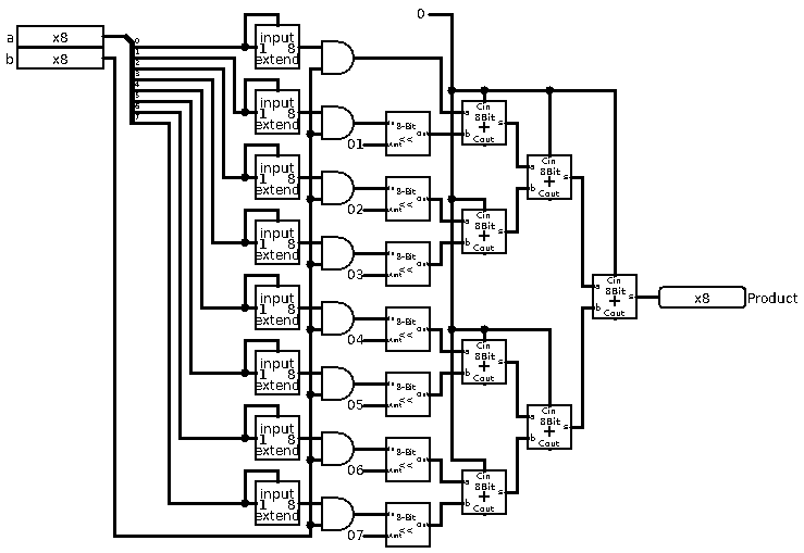
It involves lots of logical shifting (which we didn’t cover, yet) and addition. As you can see it’s a bit complex, and it’s technically not full, since 8-bit by 8-bit multiplication should yield 16-bit integer, or at least set an overflow flag or something.
Alright, but how would the software version look? Good question, let’s look at pseudo-code assembly example:
; multiply 5 by 3

    load R0, 5      ; load decimal 5 into register 0
    load R1, 3      ; load decimal 3 into register 1

mult:               ; label for our loop
    add R0, R0      ; add register 0 to itself
    sub R1, 1       ; subtract 1 from register 1
    cmp R1, 1       ; compare register 1 with 1 (sets zero flag if same)
    jnz mult        ; if zero flag is not set by cmp jump to mult

    print R0        ; 15
Something similar can be written for division:
; divide 15 by 3

    load R0, 15     ; load decimal 15 into register 0, this is our dividend
    load R1, 3      ; load decimal 3 into register 1, this is our divisor
    load R2, 0      ; load 0 into register 2, this is our result

div:                ; label for our loop
    sub R0, R1      ; subtract divisor from dividend
    add R2, 1       ; increment the result
    cmp R0, 0       ; compare dividend with 0 (sets negative flag if less, zero if same)
    jg div          ; jump if greater; if both zero and negative flags aren't set jump to div

    print R2        ; 5
As you can see we don’t cover the reminder, but you get the gist. In theory, we can provide some sort of standard library that contains routines, or even implement this in microcode (which we haven’t covered, yet).
Alright, so that covers the Arithmetic part of the ALU, now let’s move on to Logic. This is going to be pretty easy for the most part. All we need to have are AND, OR, XOR, and NOT, as well as, Logical Left and Right shifts.
The simple logical operators are super easy, it’s just 8 gates in parallel. For example an 8-nit AND gate would look something like this:
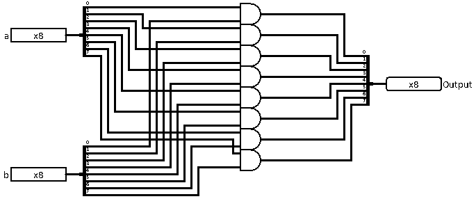
All the other ones are the same, but instead of AND gate we use the appropriate gate. But we don’t need to do this manually. In Logisim we can change the bit width of the gate so we can use built-in Logism logic gates.
Okay so now we can move to the shifting. Logical shifting is a simple operation in which we take the operand’s bits and shift all of them left or right. We can achieve this by connecting the wires from input to output, but we offset them to the next one. So input bit 0 becomes bit 1 in the output.
Here’s the right shift:
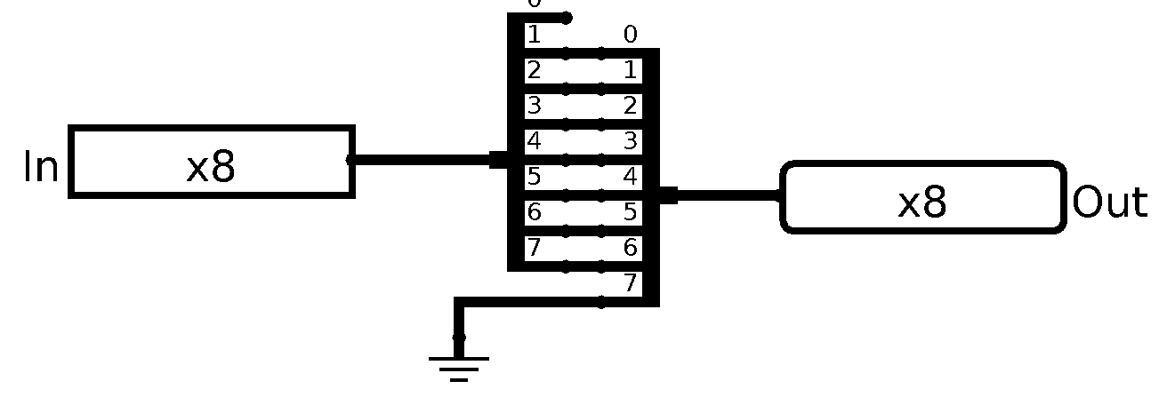
And its symbol:

And of course the left shift:
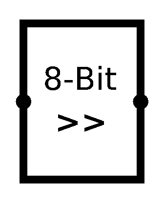
As well as its symbol:
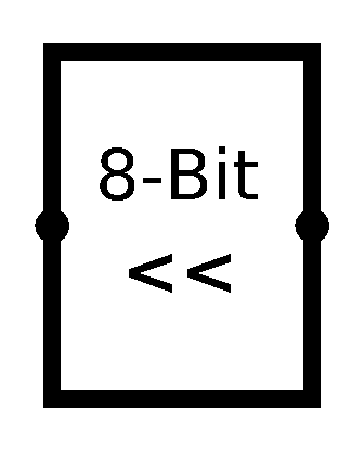
Both of them shift the input by 1 place. You can create circuits that can do more than that. You might want to just offset the inputs more, but there is a better way. We won’t use it for simplicity and consistency (with the multiplier and divider) sake. But if you want, take a look at Barrel Shifters. They use something called Multiplexer which we didn’t cover, yet. It’s a very useful gate which allows selecting different inputs depending on select bits.
Here’s an example of logical left barrel shifter I made:
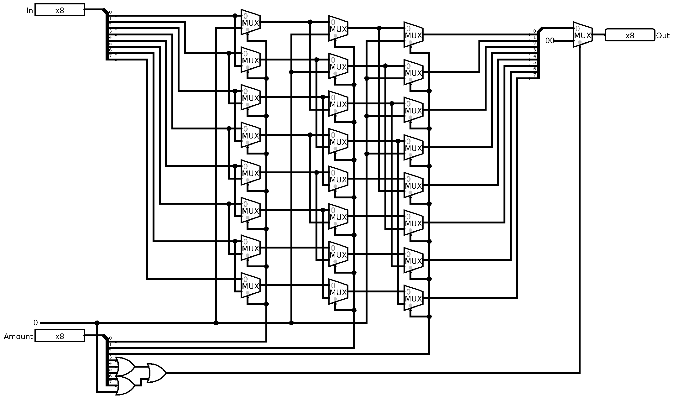
As I said we won’t use it, instead we will do same as with multiplication, we’ll do it in software:
; shift 0xFF (0b11111111) left by 3

    load R0, 0xFF   ; load hex 0xFF (dec 255) into register 0
    load R1, 3      ; load decimal 3 into register 1

shift:              ; label for our loop
    lsh R0          ; left shift register 0 by 1
    sub R1, 1       ; decrement the register 0 (sub sets zero and neg flags)
    jz shift        ; jump if zero flag is set to shift label

    print R0        ; 0xF8 (0b11111000)
Now that we have all the parts of the ALU we can wire it all together, right? Well, we need to cover one more little guy and his brother. For that we will need to jump back to transistors for a second. I am talking about Buffer and Tri-State Buffer (or Controlled Buffer). Buffer is a gate that simply pass input to output.
So, the truth table will look like this:
| in | out |
|---|---|
| 0 | 0 |
| 1 | 1 |
Boring, right? So why do we need it? Well usually it’s used to buffer signal source between different circuits. We, however, are more interested in his brother, the Tri-State Buffer. Let’s take a look at the truth table:
| in | enable | out |
|---|---|---|
| 0 | 0 | Z |
| 1 | 0 | Z |
| 0 | 1 | 0 |
| 1 | 1 | 1 |
Woah, woah, woah. What is this ‘Z’ thing? some of you might’ve thought to themselves. The Z thing is known as high-impedance or floating state. Logisim shows it as X instead of Z. What it basically means for us, is that nothing is driving that wire. Nothing is “connected” to it. Nothing is sending the signal through it. It’s neither 0, nor is it 1.
So how do we build it? Okay let’s start with buffer first, and we will keep using CMOS design here, for real world sake:
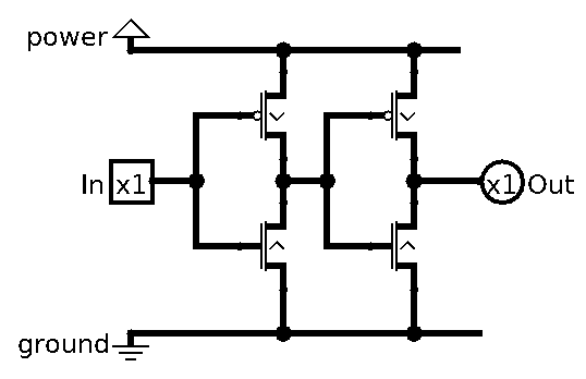
It’s basically the inverse of NOT gate. That arrangement of P-Type and N-Type transistors is basically an inverter, so by having them both stacked like that, we simply let the same signal go through (!!a == a).
The symbol for the Buffer is a simple triangle:
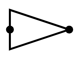
Now the good part, the Tri-State Buffer:
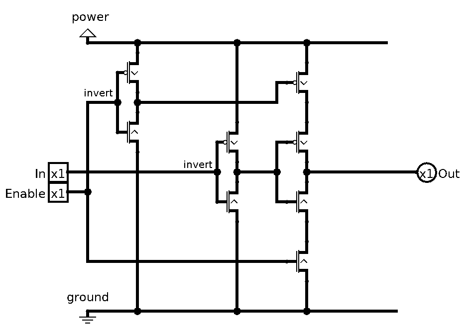
It’s a bit more involved, but it’s pretty simple. We simply close the power and ground from the output transistors, so they have neither. As you can see, I also labeled the invertors in the circuit.
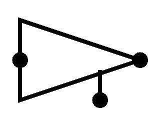
The symbol for it is the same as the Buffer one, except we have the enable pin out the bottom:
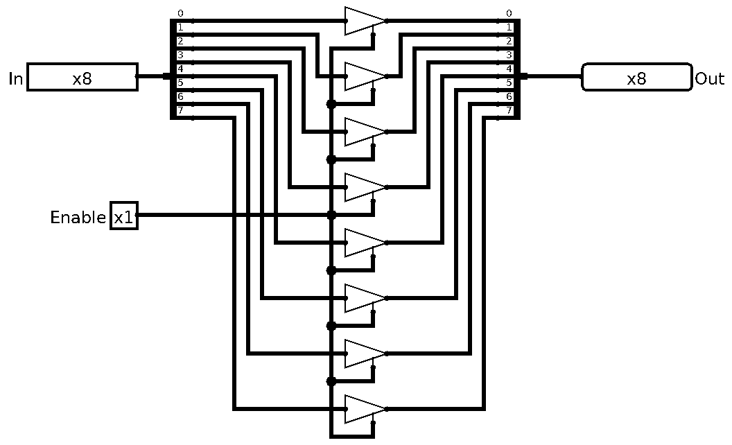
Okay so the last thing we need to do, is to use 8 of them in parallel for our 8-bit buses:
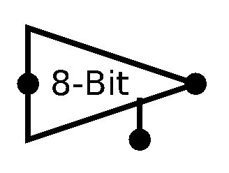
And let’s give it a symbol to differentiate it from 1-bit one:
Okay. That’s cool and all, but why do we need this again? Well, our ALU has different operators now, but it can only output one thing. So, we need a way to select which one it does. And that’s exactly why we needed Tri-State Buffers. When they are off, nothing is driving the output wires, when one of them is on, only that data is on the bus. You can think of this like this: when Tri-State Buffer is disabled, the wires aren’t “connected”, so no signal, not even 0 is going through them. We need this because bad things happen when multiple signals try to drive same wire. In Logisim it simply gives us an Error a red wire and a big E for the output. In real life I honestly never even tried that, but it can probably damage the device, basically it’s bad, and you won’t have any readable data there for sure.
Now that we have everything we need, let’s wire our ALU:
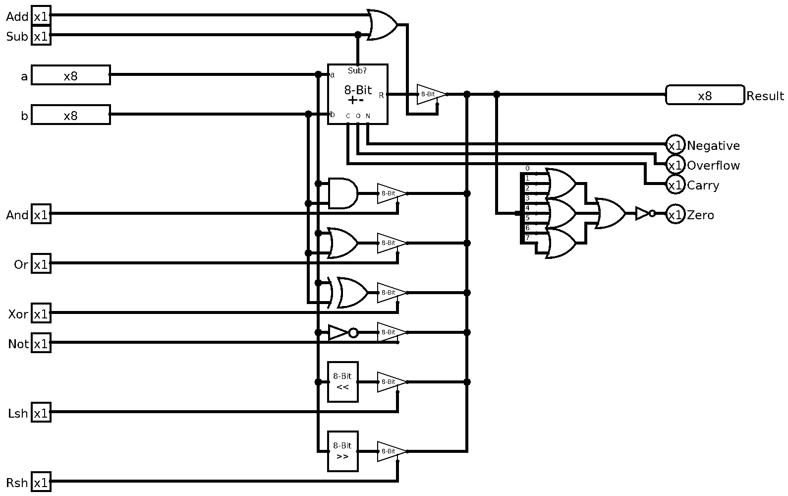
As you can see, we just combine all our operands and we use Tri-State Buffers to control what we are outputting. You may have also noticed, that I moved the Zero flag calculation from our Adder/Subtractor into the ALU proper. That’s because I think it can be useful if other operations can set it, but all the other ones are arithmetic only. One can also notice that Add and Sub signals are ORed. That’s because both of them are used in Adder so we output from it when any of them is set.
Now for the symbol of ALU. It’s usually represented as this V shaped thing, hence this is what I’ve done:
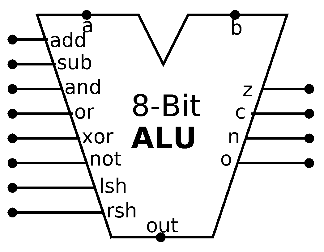
The inputs come from top, control bits from the left, flags from the right, and of course the output from the bottom.
And that’s that! We just build the muscle of the CPU, the thing that does the work! With all this operations we can do all sorts of things. But all of that will come in the future. For now play around with your newly baked ALU. Wanna go deeper? Try to implement multiplications and divisions in hardware, as well as, the barrel shifters.
Till next time!
Yey! I am back! Sorry for such a long delay between the posts, was bit busy, then Ludum Dare happened, then the dilemma “just tell the basics vs go deep”. I decided to only cover the basics for multiple reasons. It’s going to be easier and faster to produce, less technical people don’t get scared off, the deep stuff is not that necessary for understanding of the overall architecture of a CPU. Maybe after I finish this series, I can make another one that covers some optimizations.
Anyways, I hope you enjoyed this one, next time we’ll cover either overall architecture or start working on memory. Tune in next time to find out!
Oh, and the download link for Logisim circuit for this part: cpu-scratch-p4.circ I included a play area for the ALU in the main circuit.
P.S. If you find any errors, mistakes, and/or want to give me some feedback, feel free to send me an email