Let's Make a CPU: Part 5 - Flip-Flops and Registers
Previous part. If you missed the introductory post, head here: Part 0.

Last time we managed to finish the work horse of our processor, the ALU. Now we can crunch numbers and do all sorts of cool bitwise magic on them. But what good does that do for us if we can’t store it?
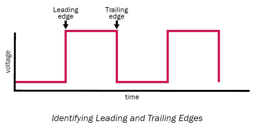
So this time, we will create our working memory, the registers. You may have noticed the weird banner on top, well it should make more sense after we’re done with the first part of this post. But really it’s just for giggles.
“Okay then, how do we store, say, a single bit?” glad you asked! We’ll use a latch also known as a flip-flop. (But they are a bit different, we’ll get to it)
Latch is a device that has 2 states, one of which represents 1/ON/TRUE bit and the other is 0/OFF/FALSE, and we can switch the state of the latch, hence, store information.
So let’s build one. For that we need 2 NOR gates:
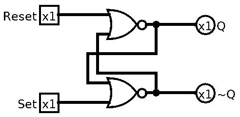
It’s called SR NOR Latch. It’s a Latch, hence the Latch, it uses NOR gates, and the SR because it has Set and Reset pins.
As you can see, we actually feed the outputs into the inputs, which as you might have guessed can cause oscillation. This is why Latches start in unknown state, and need to reset (or preset) latches at least once. Logisim will give Error before we set any value into it. Also you might’ve noticed that ~Q output, it’s complementary (opposite) of Q which is our actual output. It’s just how these Latches are made in real world, and we’re sticking to that.
Let’s improve this design a bit. At the moment to store 1 we need to set the Set input. If we want to store 0 after that we need to Reset the Latch first. But Set and Reset
are complementary, as in they are opposite. To store a 1 we need to send 2 bits 01 and to store 0 we need to send 10. No fun. We can use SR’s complementary property to our advantage. But first, as always, the symbol:
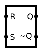
We can have single input D (stands for Data) and NOT it before it goes to Reset. Also, let’s make this new latch a gated one. What’s a gated latch? Well, at the moment any change on D pin would change the stored value. (this is why D latches are also called Delay latches, since they simply pass the same input, just delayed a bit)
Okay, so what do we do? Well, how about an AND gate before Set and Reset and 1 pin on both of them is dedicated to let the input go through. Let’s see it in action:
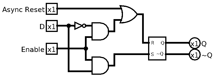
Nice, as you can see, I also added “asynchronous” Async Reset, what I mean by that, is that we can reset the latch even when Enable is 0. We do this so we can have a stable state latch whenever we want.
And the symbol for this Gated D Latch is:
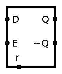
So, remember I told you that latches and flip-flops are not quite the same. Well, it’s time to tell you the difference. Latches are transparent, while flip-flops are synchronous or edge-triggered. What does any of that mean, I hear you ask. Well, before this point all our logic was so called combinational logic. That means that the output only depended on input. Kinda like pure functions. In sequential logic on the other hand, output not only depends on current input, it also depends on sequence of previous inputs. In other words it has memory, aka state. How do we tell the difference between previous signal, and next one? Well we need to somehow synchronize all the data that is going around.
And for that we use clocks. Like any oscillators, crystals and alike. This is not your clock that counts time. It’s more like device that produces 1 output every X time units. If you know what square wave is, you know what I mean. In any case, this wave has edges, where it starts, and where it ends.
So what does all this have to to with latches and flip-flops? Well, latches are transparent, aka, they change output immediately on input change. We want it all be in sync, so we can easily move data from one part of the CPU to another. Hence why we want flip-flops not latches. We want them to change their state only on clock change.
How do we do that? Well we kinda did that already (sneaky I know), the Enable input only allows the data to change when it’s high/1. But to have better control over this we use 2 D latches to make 1 flip-flop:
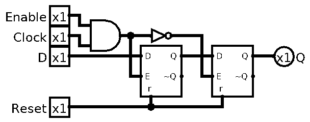
As you can see, the 2nd latch only triggers when clock is going from high to low, so this would be Falling Edge Triggered D Flip-Flop. I also added back the Enable pin by ANDing it with the Clock. The 1st latch there is acting like a buffer before the clock edge actually fall.
And let’s give it a symbol:
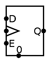
See that weird illuminati triangle/arrow symbol? That’s how people usually mark clock pins. So I just follow that for consistency.
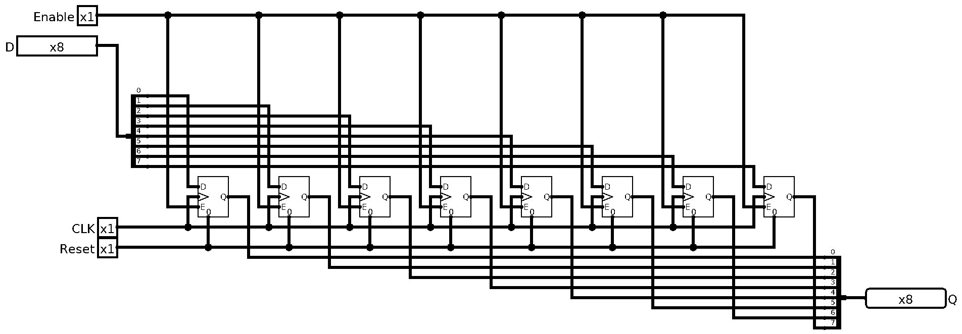
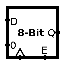
Okay now that we have 1-Bit storage, let’s scale it to our WORD size, 8 bits, a byte. We call it a WORD, because in ye olde days, we called a natural unit of data that CPU can operate on a MACHINE WORD, and it’s size was however long the word was in bits. So for us it’s a Byte, or Octet (Since bytes weren’t always 8 bits long too).
Anyways, we can just have 8 D Flip-Flops with control lines connected together, pretty easy:
And as always, the symbol:
Now that’s all the memory we need internally for a CPU. We can have a bunch of register to store some values. But what if want to store much more values? We’d need something we could access randomly, too. So we can have any value. Hmm… So how do we build this… RAM?
Well, you’ll have to tune in next time, because this is getting a bit long.
For now, feel free to play around with current CPU:
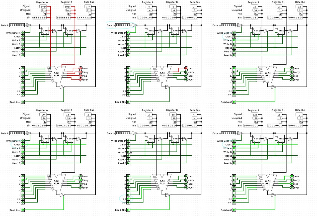
Okay, so that’s the basics of memory. I decided to split it in 2, because it’s getting long. Next time we’ll make RAM, address the problem of addressing and have ⅔ of the CPU done. As always Logisim schematics: cpu-scratch-p5.circ
P.S. If you find any errors, mistakes, and/or want to give me some feedback, feel free to send me an email
